Your cart is currently empty!
Tag: DSC
-
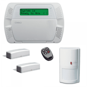
Adding Wireless Sensors To A DSC PowerSeries Alarm System
[row] [col span__sm=”12″ align=”center”] [ux_image id=”163975″ width=”41″]
How To Add Wireless Sensors To My DSC PowerSeries Panel
[/col] [/row]
Adding wireless sensors to a DSC PowerSeries panel is not difficult assuming you have a wireless receiver installed which can be a standalone receiver attached to the panel (RF5132-433 for example) or integrated into a keypad (such as the RFK5500). Obviously a wireless receiver (433Mhz) for standard PowerSeries panels that begin with PC or 915Mhz PowerG for Neo panels which start with HS.
The first step is determining the firmware version of your panel since the instructions are different depending on value. For firmware versions V4.6 and above or a NEO panel use Method 1. For standard PowerSeries panels that are V4.5 and below use Method 2. Look on the motherboard for a GREEN sticker which will show model and firmware version. Method 1 is definitely easier but not supported on the older panels.
[ux_image id=”82154″ width=”37″] [gap]
Method 1 (Section 898) For Neo and PowerSeries V4.6 and higher only
- Enter Program Mode: Enter *8 + [Installer Code]. The red lock light will illuminate and Section will display depending on keypad style. The default Installer Code is 5555 or 6321.
- Enter Wireless Enrollment Mode: Enter [Section 898]
- Enroll Wireless Sensor: Trip the sensor by tampering (opening the case on the transmitter or moving the magnet away for door contact for example
- The ESN will display after tripping the sensor. Confirm the ESN with tag on transmitter. Press * to confirm
- Enter zone number to be used: Enter two digit zone number such as 13 or 07. If a wireless keyfob enter 2 digit keyfob number such as 01 for first keyfob in system.
- Repeat for multiple sensors otherwise press # when finished.
- Exit Program Mode: Enter # # #
- Test the sensor to be sure its registered and working as expected
[gap]
Method 2 (Section 804) For PowerSeries firmware V4.5 and below
- Enter Program Mode: Enter *8 + [Installer Code]. The red lock light will illuminate and Section will display depending on keypad style. The default Installer Code is 5555 or 6321.
- Enter Zone Type in [Section 001 to 004]. [Section 001] will have either 8 two digit entries or 16 depending on model panel. Common types are 01=Exit/Entry, 03=Perimeter, 05=Motion.
- Program Zone Attributes: Enter [Section 101] thru [Section 132] and be sure “8” is ON for wireless. For example [Section 101] is for Zone 01, [Section 105] is for Zone 05.
- Program Partition for wireless sensor: Enter [Section 202] through [Section 205] for Partition 1 zones. Enter [Section 210] through [Section 213] for Partition 2 zones.
- Enroll Wireless Device. Enter [Section 804] and enter 2 digit zone number such as 08.
- Enter the 6 digit ESN number on the wireless device. If your panel is looking for an 8 digit ESN then add 00 to the beginning of the 6 digit ESN.
- Repeat for multiple sensors otherwise press # when finished.
- Exit Program Mode: Enter # # #
- Test the sensor to be sure its registered and working as expected
-
Adding an Alula BAT-CONNECT to a DSC Panel
[row] [col span__sm=”12″ align=”center”] [ux_image id=”76676″ width=”75″] [ux_text text_align=”left”]
Overview
The Alula BAT-CONNECT is a very flexible Ethernet, WIFI, and 4G/5G LTE cellular communicator that can connect with many different system brands and models. This post covers connecting the Alula BAT-CONNECT to a DSC PowerSeries alarm panel.
NOTE: The Alula BAT-CONNECT cannot be used with DSC NEO panels.
The DSC models supported for interactive service (remote control) are:
- DSC PC580 (Power 432)
- DSC PC1555 (Power 632)
- DSC PC1555MX (Power 632)
- DSC PC5010 (Power 832)
- DSC PC5020 (Power 864)
- DSC PC1616
- DSCPC1832
- DSC PC1864
Keep in mind many older alarm panels can also be connected for Internet and/or cellular alarm monitoring using the BAT-CONNECT but interactive service (remote control) may not be supported.
ANY panel that can use ContactID format for communications will work with the BAT-CONNECT for alarm monitoring. Most panels made from the late 90’s to today can use ContactID format which is what most modern central stations prefer today. The BAT-CONNECT however requires ContactID input from your alarm panel for transmission to Alula and our central station.
[/ux_text] [ux_image id=”160324″ width=”32″] [ux_text text_align=”left”]
Step 1 – Test Your Installer Code
You will need to know your panel’s Installer Code because without it no dealer can sign you up for new monitoring service. This code is used to get into the programming fields necessary to modify the central station account number, and telephone numbers for example. In many cases we can remotely program the panel for service setup but we’ll need the Installer Code to make any changes.
If you don’t know the Installer Code you can try the default Installer Code for DSC which is 5555. Just enter *8 [Installer Code] and if you get a long beep then the default code has been changed. You can also try 5010 (older DSC panels) and 6321 (installed by ADT). If the red lock light comes on or the keypad displays “Section” then the Installer Code you tried works. Just hit # to exit Program Mode.
The other method is to call your previous dealer to get the Installer Code. If they programmed the panel for central station monitoring they know the Installer Code for your panel.
You can also reset the DSC Installer Code but this means the entire panel will need to be reprogrammed from scratch which can be a big job and usually done by a trained installer. Always better to get the Installer Code from the previous dealer when you can!
[/ux_text] [gap]
Step 2 – Create Your Alula Account With SafeHomeCentral
Step 2a – Sign up for one of our Alula alarm monitoring plans.
Pick the plan you want (and options such as video), Add to Cart, then Checkout. Click HERE for our Alula Plans.
Step 2b – Complete our Monitoring Enrollment Form.
Complete the Monitoring Enrollment Form online for the UL central station and be sure to include the MAC and CRC shown on a sticker inside your BAT-CONNECT. The MAC and CRC are used to identify and register your specific Alula communicator. Click HERE for our Monitoring Enrollment Form.
Even with Self-Monitoring plans we need an electronically signed Monitoring Enrollment Form with your MAC and CRC address to create your account.
[ux_image id=”159818″] [gap] [ux_text text_align=”left”]
Step 3 Program Your Panel To Work With The BAT-CONNECT
DSC panels require little advance programming to make work. We will remotely setup the BAT-CONNECT once hooked up and online. However the keypad lockout setting MUST be changed before powering up the BAT-CONNECT.
-
- Enter Program Mode: *8 [Installer Code]. The default Installer Code is generally 5555 unless changed by a dealer.
- Once the red lock light is on (in Program Mode) enter 012 for Section
- For data enter 0 #
- Exit Program Mode: Enter ###
[/ux_text] [gap]
Step 4 – Connect Your BAT-CONNECT To Your DSC PowerSeries Panel
The inside door of your alarm panel’s metal box always has a wiring diagram. Confirm your panel’s terminals conform to the diagram below. This is how the BAT-CONNECT will be wired to the terminals in your metal box. We recommend the 6 wire hookup as shown.
You will need to supply your own 22 gauge wire available at any hardware store and sold by the foot. Get a 5 foot length of 4 conductor 22ga cable which is four 22 gauge colored wires in a single plastic outer cover.
NOTE: Alula does not supply hookup wire with their communicators.
[ux_image id=”159998″ width=”33″]
Step 4a – Power Down Your System
Always work on a powered down system! There is little chance of physical danger to you but electronic components can easily be damaged if shorted while making connections.
-
- Unplug the backup battery in the metal box. Disconnect the RED or BLACK wire. They just slip off the battery terminals.
- Unplug the AC transformer that is plugged into the 120VAC outlet near your metal box with all the alarm wiring. If in a closet the transformer may be plugged in in another location such as a basement, attic, garage since most closets do not have an AC outlet.
- Worse case if you can’t find the transformer CAREFULLY disconnect Terminal 1 (far left side labeled AC) in the metal box. Do NOT let this wire touch Terminal 2 or you will short out your transformer and will need to replace it! There is always a wiring diagram on the inside door of your panel’s metal box. Confirm that Terminal 1 and 2 connect to your 16.5VAC transformer.
- Confirm the panel has been powered down by checking the keypad. It should be dark (OFF)
[row_inner style=”collapse” width=”full-width”] [col_inner span=”6″ align=”center”] [ux_image id=”159988″ width=”56″] [/col_inner] [col_inner span=”6″ align=”left”] [ux_image id=”159987″] [/col_inner] [/row_inner] [gap]
Step 4b – Mount Your Alula BAT-CONNECT To The Wall
The BAT-CONNECT is generally mounted next to or above the metal box. If in a basement and reception is weak mount the BAT-CONNECT as high as possible and as close as possible to an outside wall to get the best cellular signal. In some cases you may need to locate the BAT-CONNECT on the first floor or higher to get a good signal if in a poor reception area. Be sure to buy enough wire if not mounting next to the metal box!
NOTE: Never place the BAT-CONNECT inside your metal box since this will seriously impact cellular reception.
[ux_image id=”159809″ width=”40″] [gap]
Step 4c – Wire Your BAT-CONNECT To Your DSC Panel’s Terminals
Always check the wiring diagram on the inside door of your metal box for exact terminal numbers if different from the below diagram. Connect all six wires as shown. Four wires for the virtual keypad function and two wires for telecom Tip and Ring.
[ux_image id=”160327″ width=”64″]
Step 5 – Power Your DSC Panel and BAT-CONNECT
Connect the AC transformer (or Terminal 1) and connect the leads to your 12VDC backup battery. Confirm the LEDs are lit on the BAT-CONNECT. If using cellular service then you must have at least 2 bars shown for reliable service.
If using Ethernet plug in your patch cable and the Ethernet LED will come on the cellular LED will go off.
If using WIFI unplug the Ethernet cord and press the WPS button on your router and then press the WPS button on the BAT-CONNECT to create a secure connection automatically.
NOTE: If your router does not support WPS then we can enter your SSID and key in manually from our dealer portal.
[ux_image id=”162116″ width=”47″] [gap]
Step 6 – Test Your BAT-CONNECT
This last step is to make sure everything is working as expected. Your BAT-CONNECT will discover all your wired and wireless zones on your panel once powered up AND each zone triggered (open a door or walk in front of a motion detector). The alarm does NOT need to be armed.
One of our SafeHomeCentral Tech Support agents will supply you with your Alula login (if using interactive services).
They will ask you to arm your system system using your Alula app (if interactive services selected) then trip an alarm to make sure both Alula and our central station is receiving the alarm event (zone number, type of alarm, account number).
You are now ready for service!
[ux_image id=”98822″ width=”27″] [/col] [/row]